
It’s now winter here in the UK, and like many people, I’ve noticed an increase in condensation on windows and some external walls in some areas of my home. So I decided to purchase a number of Sonoff temperature and humidity sensors to help me get a sense of the humidity levels throughout my home.
The Sonoff temperature sensors are Zigbee devices, and can communicate metrics across a Zigbee network. Zigbee is a mesh network protocol used by low-power IoT devices like temperature sensors, smart lightbulbs etc. Zigbee networks require a coordinator to coordinate how all the Zigbee devices on the network should communicate with one another. The coordinator often also serves as a bridge between a zigbee network and a standard Wi-Fi or ethernet network.
In my case, I decided to purchase a Sonoff Zigbee Bridge Pro. I specifically chose this device because it is relatively cheap, but also because it is based on the ESP32 microprocessor, which means it is flashable with open source firmware such as Tasmota and ESPHome. Flashing with custom firmware opens up various options for integrating with things like Home Assistant or an MQTT broker, and avoids having to send data to a proprietary cloud service such as the eWeLink Cloud that you would otherwise have to use with Sonoff devices.
I chose to flash the Sonoff Zigbee Bridge Pro with Tasmota. In this post, I will document the process I followed to do this.
Connecting to the Sonoff Bridge’s UART serial pins
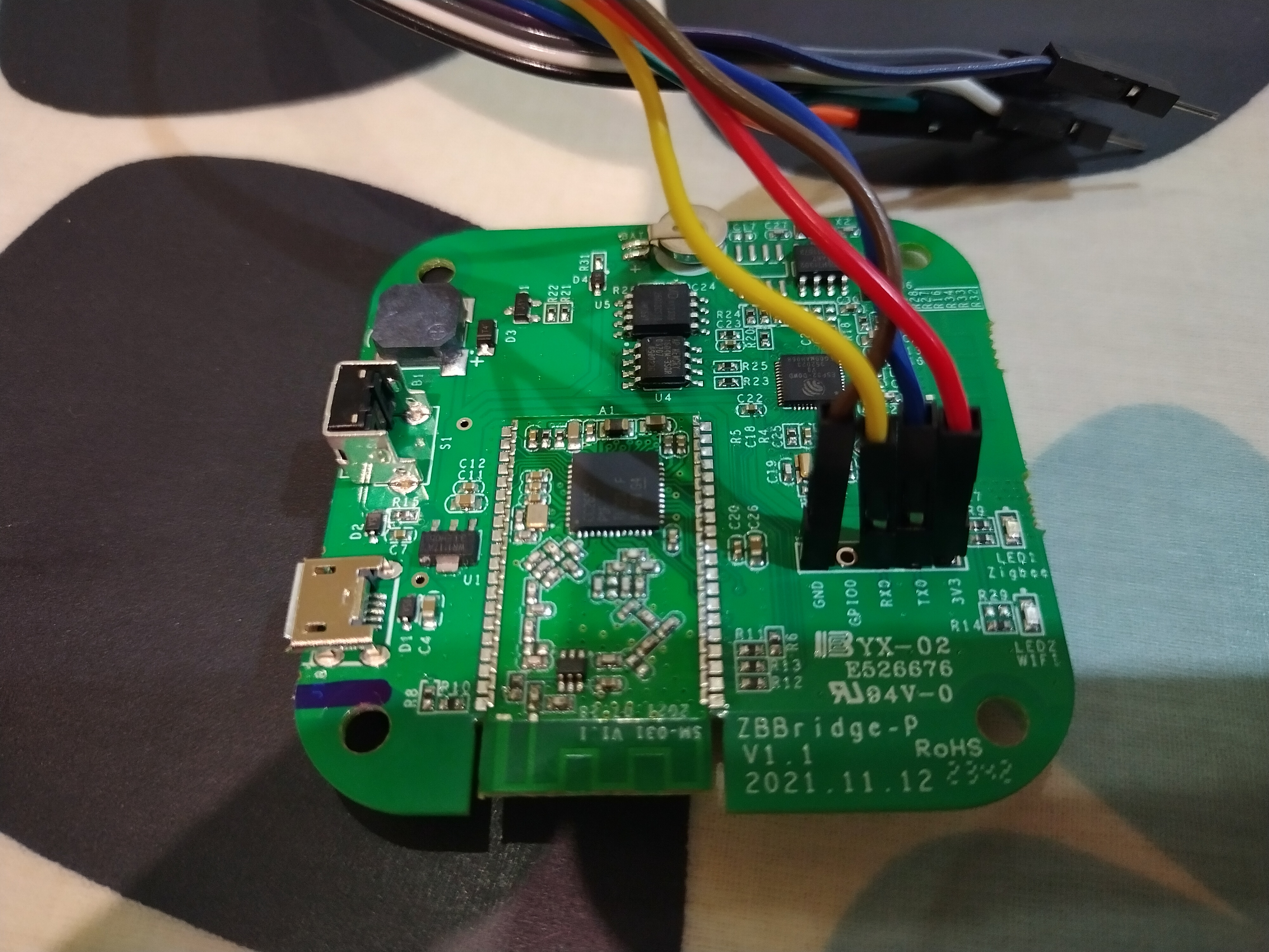
To flash the Sonoff Zigbee Bridge Pro you need to connect to the UART serial pads on the PCB. Open up the device by removing the four little screws under the rubber feet on the back of the unit.
There are 5 pads on the PCB labelled GND, GPIO, RX, TX and 3V3. You
can connect to these pads from a computer using a USB-to-TTL serial adaptor such as
a CP2102
or a PL2302. You’ll
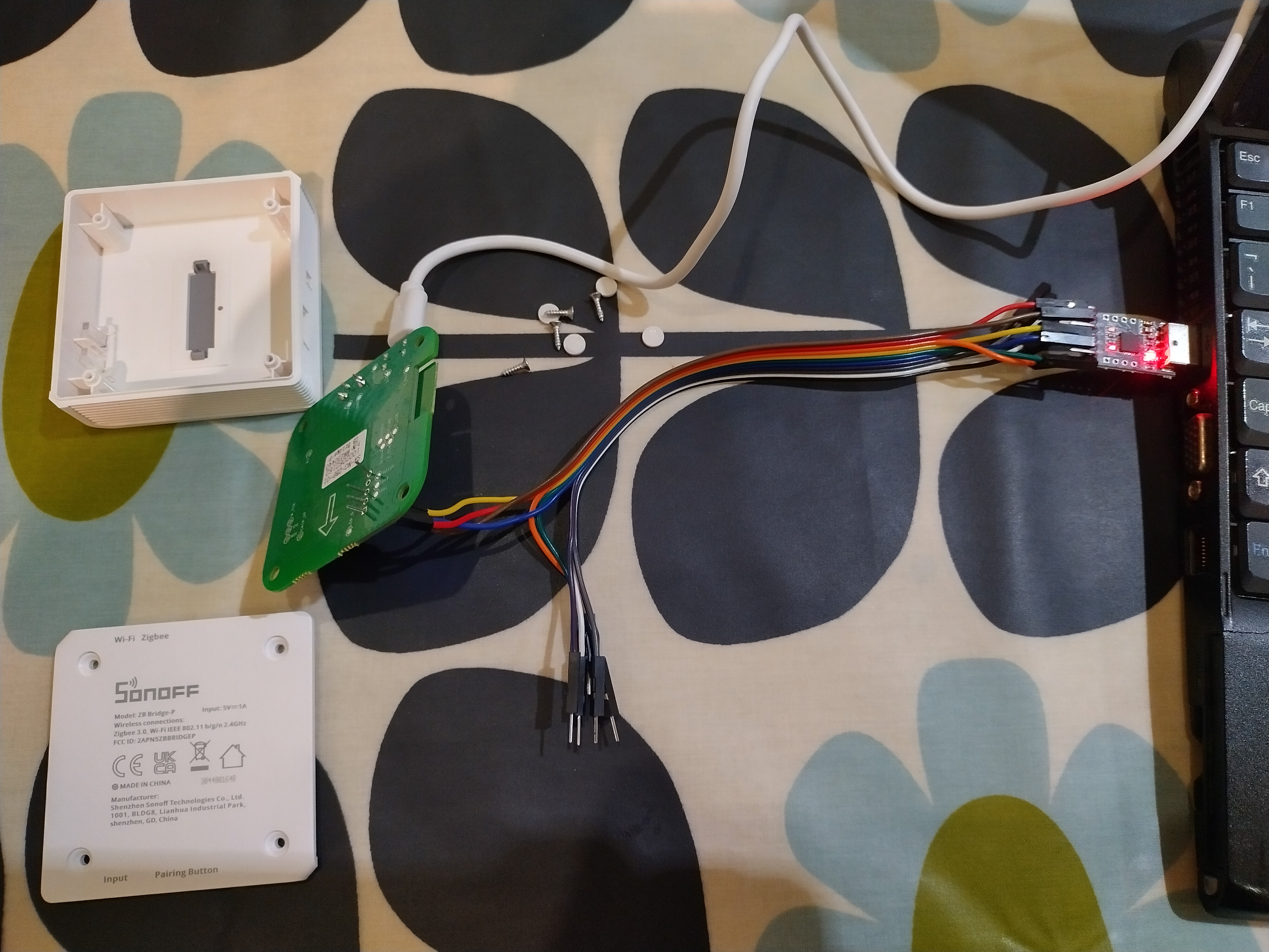
also need some Dupont cables to connect the serial adapter to the pads on the
Sonoff Bridge; I used male-to-female Dupont cables - the pins on the male end
fit into the pads on the PCB, but you can also solder a 5-pin header onto the
PCB for a better job.
You will need to connect up the pins on the Sonoff Bridge to the TTL adapter as follows:
| Sonoff Zigbee Bridge Pro | TTL serial adapter |
|---|---|
| GND | GND |
| GPIO | GND (when powering on) |
| RX | TX |
| TX | RX |
| 3V3 | 3V3 (3V) |
Note, be very careful to connect to the 3V pin on your TTL serial adapter and not the 5V pin! Some adapters have separate pins for these as mine does, but yours might have a jumper to determine what voltage is provided. If you use 5V you will fry the components on the Sonoff Bridge, so be careful here!
Also, note that you need to connect the RX pin on your adaptor to the TX pad
on the PCB and the TX pin to the RX pad on the PCB.
To put the Sonoff Bridge into flash mode you have to short the GPIO and GND
pads for a few seconds when powering on the device. I did this by touching both
pads with a screwdriver.
Prep for flashing
Download the tasmota image
Next you need to download the tasmota32-zbbrdgpro.factory.bin image from the
tasmota GitHub
project.
This image is built specifically for the Sonoff Zigbee Bridge Pro and contains
all the files needed to get the device working with tasmota. You could use one
of the more generic images, but you’d need to follow extra steps to get it
working, so I strongly recommend you use the zbbridgpro one.
Install the esptool flashing tool
There are a number of utilities that you can use to flash the device, including
a number of graphical tools. However, I find that the simplest way is to use
esptool, which is a commandline utility created by Espressif for flashing ESP
microprocessors.
On Debian based systems you can install esptool using apt:
$ sudo apt install esptool
Flash the Bridge
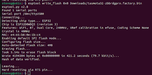
If you’ve successfully put the Bridge into flashing mode, you should now be able to flash it with the tasmota image you downloaded above:
$ esptool write_flash 0x0 tasmota32-zbbrdgpro.factory.bin
This will take several minutes to complete. If all went well you should see console output like the following:
Configuring tasmota
Unplug the serial USB adapter and remove the dupont cables, then power up the
bridge by plugging in the USB cable. If tasmota flashed correctly you should see
a Wi-Fi access point called something like tasmota-XXXXX-XXXX when you scan
for networks on your phone or laptop.
Connect to the access point with a phone or laptop and browse to 192.168.4.1.
Tell tasmota which Wi-Fi network it should connect to and give it the Wi-Fi
password.
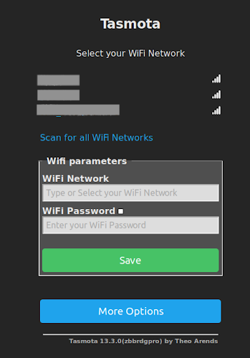
Once you hit Save it will try to connect to your network, and if successful it will try to redirect you to an IP address on your Wi-Fi network.
Device configuration
You would usually need to configure the device in Tasmota. However, the
tasmota32-zbbrdgpro.factory image comes pre-configured with the correct
settings. You can see this by browsing to Configuration -> Auto-configuration.
The device should appear as Sonoff ZBPro, but if it doesn’t you can select it
from the device list and click “Apply configuration”.
If needed, you can also supply the following config by browsing to Configuration -> Configure other:
{"NAME":"Sonoff Zigbee Pro","GPIO":[0,0,576,0,480,0,0,0,0,1,1,5792,0,0,0,3552,0,320,5793,3584,0,640,608,32,0,0,0,0,0,1,0,0,0,0,0,0],"FLAG":0,"BASE":1}
Flashing the coordinator firmware onto the Zigbee chip
At this point we have flashed the tasmosta firmaware onto the device. We can now do one of three things; we can:
- Use something like Home Assistant’s ZHA integration to control the Sonoff Bridge Pro and act as a Zigbee coordinator
- Use Zigbee2MQTT to take control of the Sonoff Bridge Pro and act as a Zigbee coordinator
- Flash the Sonoff Bridge Pro’s CC2652 Zigbee chip with Tasmota’s Zigbee coordinator firmware and allow it to act as a Zigbee coordinator (known as Zigbee2Tasmota)
Options 1 and 2 require a separate device such as a Raspberry Pi running something like Home Assistant and possibly Zigbee2MQTT and an MQTT broker such as Mosquitto. If you have something like this already, ZHA or Zigbee2MQTT are excellent options, and in both cases they take control of the Zigbee chip on the Sonoff Bridge Pro using serial over TCP; Tasmota will simply pass bytes between the coordinator and the Zigbee chip. However, the downside of this is that it couples your Zigbee network to the device running ZHA/Zigbee2MQTT, and if that goes down so will your Zigbee network.
Option 3 does not require additional hardware; it turns the Sonoff Bridge Pro into a Zigbee coordinator, and with Tasmota’s built in web interface you can use the device as a light weight Zigbee hub.
It is also possible with Zigbee2Tasmota to integrate your Zigbee devices into Home Assistant with Home Assistant’s Tasmota integration. In this configuration, you would configure Tasmota to send events to an MQTT broker. This is not documented here.
I chose to go with option 3 and flash the Sonoff Bridge Pro’s Zigbee chip with the Tasmota coordinator firmware.
Flashing the coordinator firmware
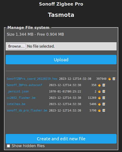
The files needed to flash the coordinator firmware are already included in the
tasmota32-zbbrdgpro.factory.bin image. You can see these in Consoles -> Manage
File System:
The flashing procedure is carried out from the Berry Scripting console. Go to
Consoles -> Berry Scripting.
First, verify that the hex file is okay by doing:
import sonoff_zb_pro_flasher as cc
cc.load("SonoffZBPro_coord_20220219.hex")
cc.check()
If the files is okay you should see the following in the console output:
FLH: Starting verification of HEX file
FLH: Verification of HEX file OK
You can now flash the coordinator firmware by doing:
cc.flash()
This will take 5 minutes or so to run, during which time tasmota will be unresponsive. Once back the console should show something like:
02:35:29.888 FLH: cc2652_flasher rx=23 tx=19 rst=15 bsl=22
02:35:29.916 FLH: Flashing started (takes 5-8 minutes during which Tasmota is unresponsive)
02:39:35.038 FLH: Flashing completed: OK
02:39:35.155 FLH: Flash crc32 0x000000 - 0x2FFFF = bytes('1598929A')
Restart the device by power cycling it, and when back up the console should report something like:
02:42:59.210 RSL: RESULT = {"ZbState":{"Status":3,"Message":"Configured, starting coordinator"}}
02:43:05.011 RSL: RESULT = {"ZbState":{"Status":40,"NewState":9,"Message":"Started as coordinator"}}
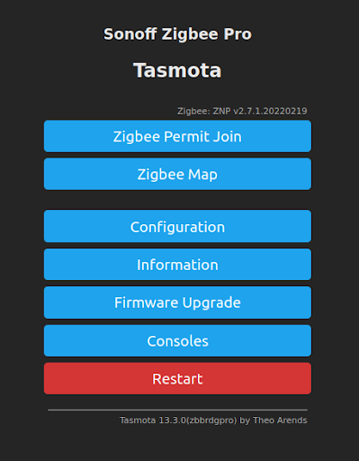
The main menu should now show the Zigbee Permit Join and Zigbee Map options:
Pairing zigbee devices
If the above steps all worked correctly, your Sonoff Bridge Pro will now work as a Zigbee coordinator. You can now pair it with any Zigbee devices or sensors you may have. For example, I have a number of Sonoff temperature and humidity sensors.
First, click the Zigbee Permit Join button in the Tasmota web UI. Now, put the
Zigbee sensor in pairing mode - on the SNZB-02 sensors this is done by pressing
the button on the sensor for 5 seconds.
The device should now appear on the Tasmota main menu showing the most recent sensor readings, as well as the battery power and LQI (which is the Zigbee connection quality).
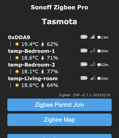
The device name will usually appear as a hexadecimal string like 0xDDA9. To
change it to something more friendly, do the following in the console:
zbname 0xDDA9, myfriendlyname
Note the comma after the device name! If successful, the console will show something like:
13:08:55.833 CMD: zbname 0xDDA9, myfriendlyname
13:08:55.839 RSL: RESULT = {"0xDDA9":{"Name":" myfriendlyname"}}
13:08:58.342 ZIG: Zigbee Devices Data saved in File System (53 bytes)